How Midea enhanced washing machine production with Visual Components
See how Midea used Visual Components to increase the capacity and flexibility of a high-end washing machine assembly line, while reducing costs by 15%.
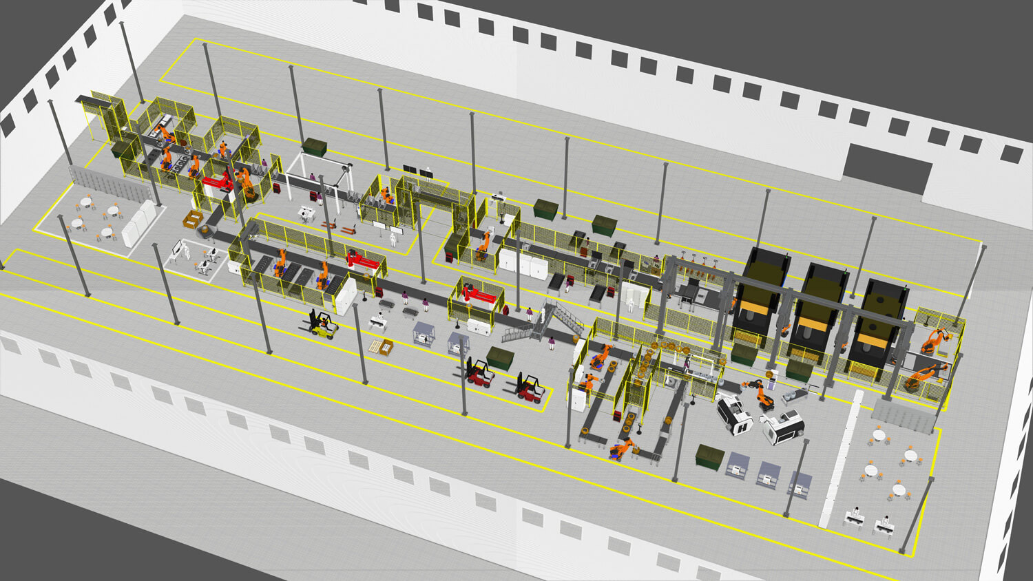
In this case study, we’ll show you how Midea, the world’s largest producer of major appliances, used Visual Components to increase the capacity and flexibility of a high-end washing machine assembly line, while reducing costs by 15%.
Download the full case study in PDF here.
The world’s largest producer of major appliances
Established in 1968 and headquartered in Southern China, the Midea Group is the world’s largest producer of major appliances and #1 brand of air-treatment products, air-coolers, kettles, and rice cookers. Its Laundry Appliances Division includes a Digital Center, which consists of a team of simulation engineers responsible for verifying the product, mold, and equipment designs, as well as robotics, logistics, and factory layouts.
A unique project with vomplex demands
In 2018, the Midea Group initiated a project to launch a flexible assembly line producing high-end washing machines. The new assembly line was to be constructed in the Wuxi factory of Midea’s Laundry Appliances Division in Wuxi, China. In addition to producing high-end, high-quality washing machines, Midea wanted the line to be capable of accommodating orders of personalized and customized washing machines. The simulation team was responsible for verifying the designs and layout of the assembly line and providing feedback on how it could be optimized.
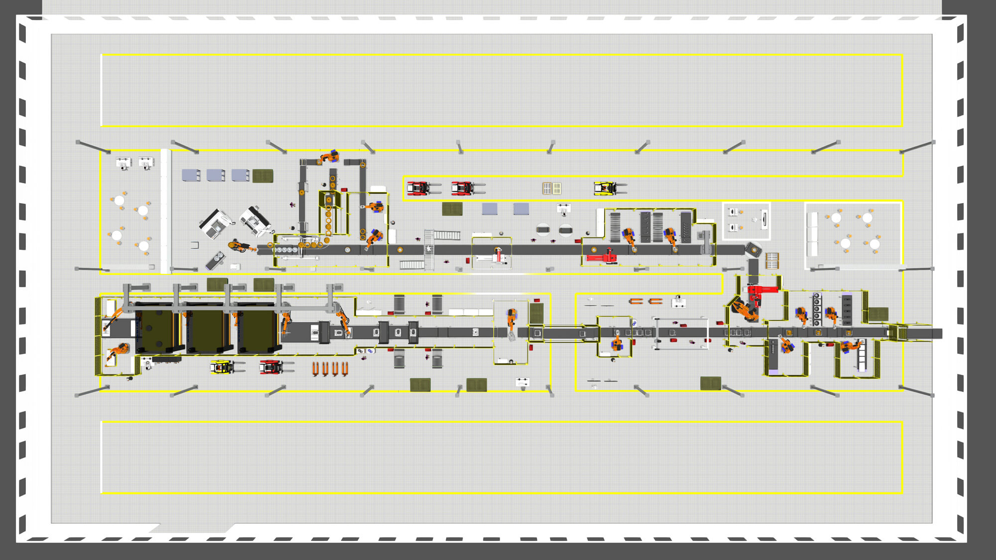
While the gross profit margin on these high-end washing machines was higher compared to the washing machines Midea was already producing, the production requirements were more strenuous. There were higher technical control requirements in terms of materials, processes, and finished products. Due to the complex production and scheduling requirements, the assembly line needed to make more use of smart manufacturing capabilities and provide a flexible production capacity.
A unique aspect of this project was that the assembly line needed the capacity to produce more than 10 different product platforms and over 100 SKUs at the same time — all mixed and with their own individual processing times, materials requirements, and quality control procedures. This involved the rearrangement of more than 100 working processes, which were totally different from the mass-production patterns used previously.
Making the switch to Visual Components
“As a comprehensive and professional simulation tool, Visual Components played a very important role in this project,” said Kong Fanshi, Ph.D, a simulation engineer on the Digital Center team. “Previously, we were using three different products to build 3D layouts and verify equipment, logistics, and production capacity.”
The product Kong and his team were using to create CAD models and 3D layouts was burdensome, especially for modeling complex machines and equipment. The extensive library of parametric and re-usable models included in the Visual Components e-catalog simplified model building for Kong and his team.
Another challenge they faced was lack of compatibility between their CAD software and equipment simulation software; importing models wasn’t easy. Once they were able to import the geometry, defining the motions and behavior of the models was complex. They experienced similar challenges with their logistics simulation tool; complex programming and time-consuming work. They found modeling equipment and processes with Visual Components to be much faster and easier. They also liked the high-quality graphics and video output.
After a brief trial period, Kong’s team was using Visual Components as their primary simulation tool.
“As it became clear that Visual Components offered many more advantages compared to these other products, we gradually turned to the software to simulate most of our project cases,” explained Kong.
Kong and his team used Visual Components to design, optimize, and verify the process and production feasibility of the layout for the washing machine project, as well as to dynamically present the planned assembly line and logistics layout to Midea executives and project stakeholders.
As a comprehensive and professional simulation tool, Visual Components played a very important role in this project.
Kong Fanshi, Ph.D, – Simulation Engineer on the Digital Center team, Midea Group
Verifying the design and layout of the assembly line
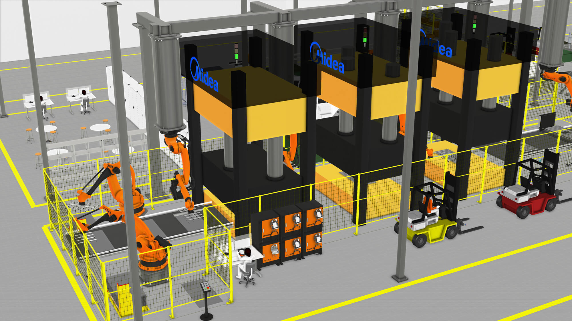
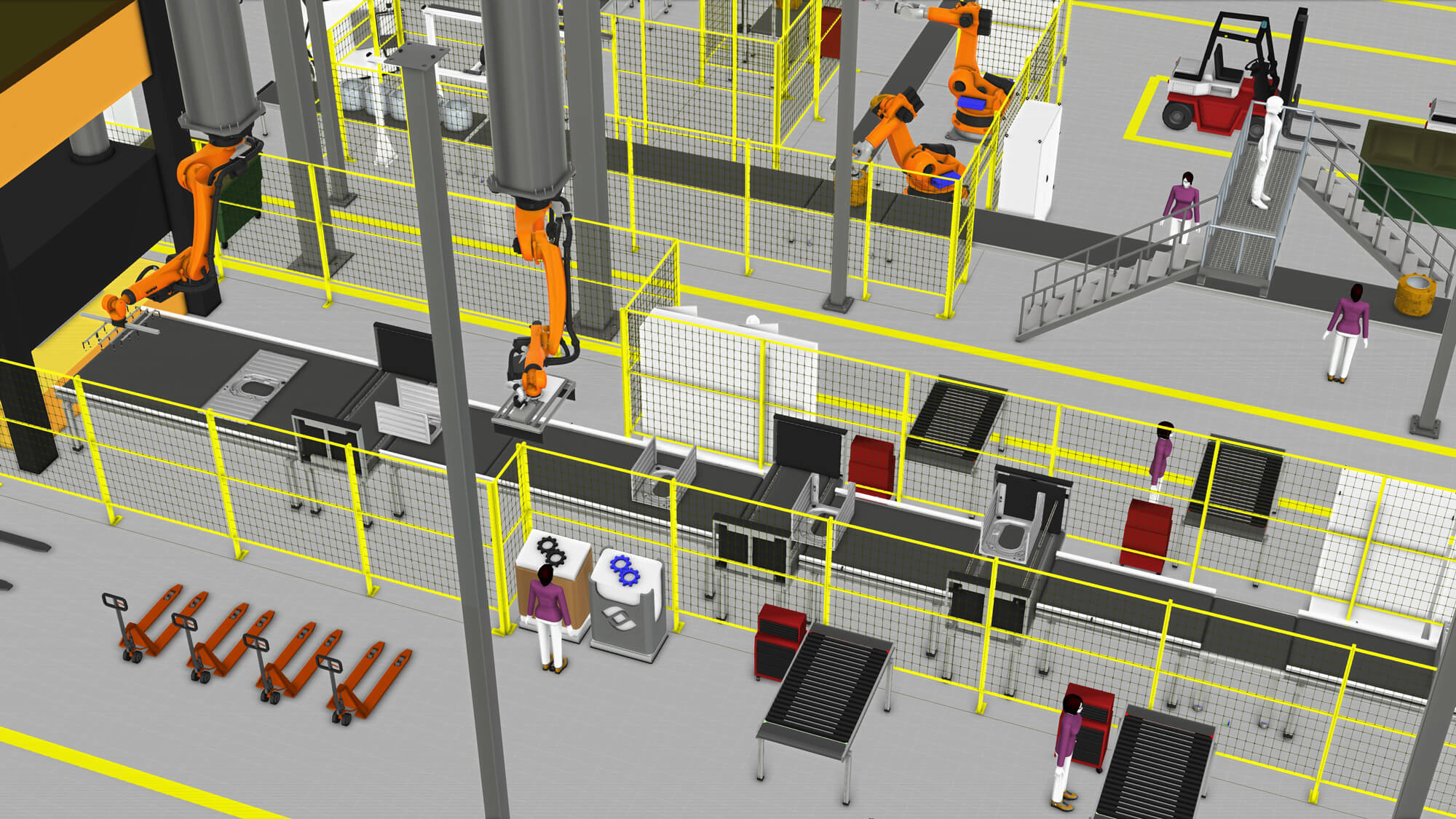
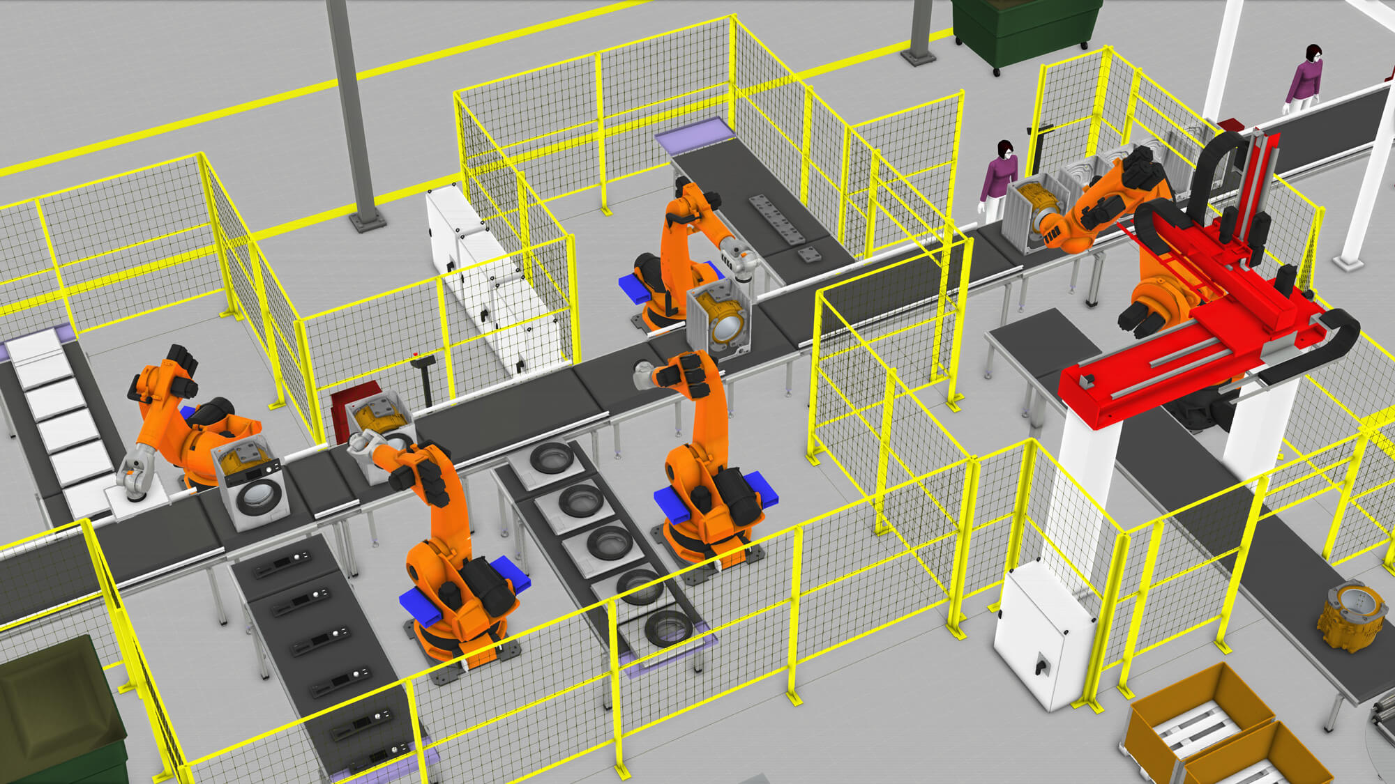
More than 100 components need to be assembled to produce a high-end washing machine. The entire assembly line project consisted of three main assembly lines:
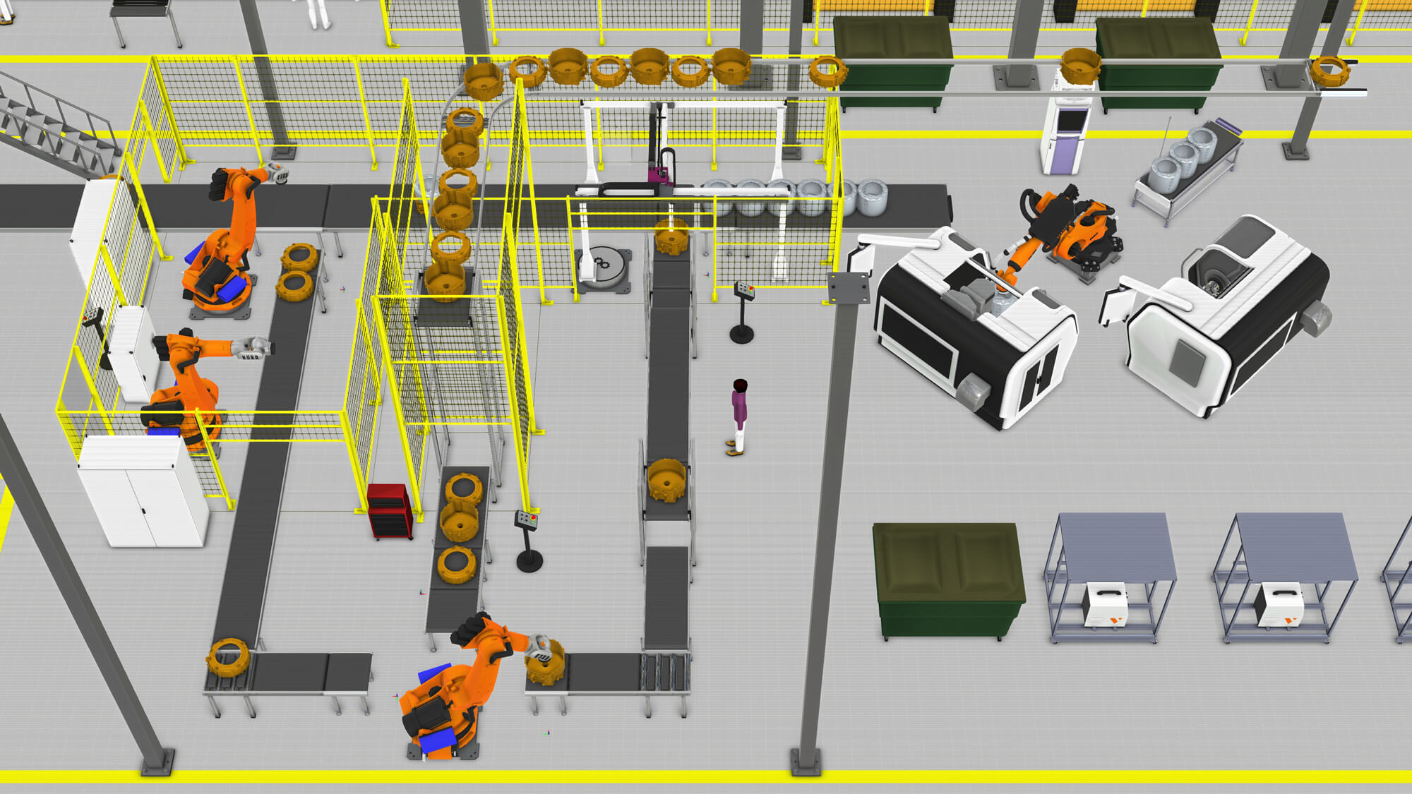
1. Tub assembly
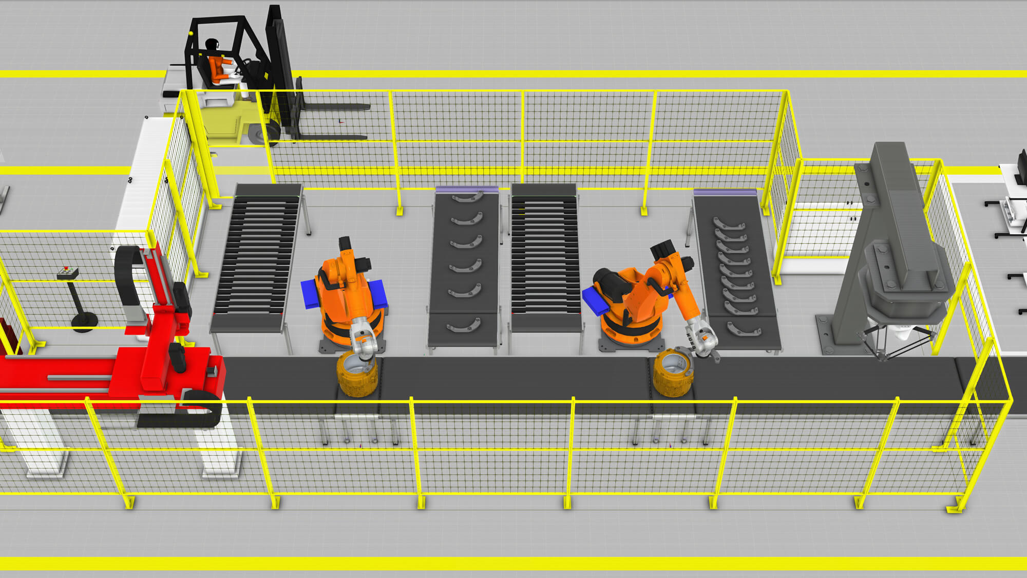
The tub assembly is formed by placing an inner tub into a back tub and then sealing it with a front tub.
2. Box assembly
A steel plate is formed into a steel box using a horizontal punching machine. Accessories such as flexible pipes and wires are installed on the box, forming the box assembly.
3. Washing machine assembly
The tub and box assemblies, along with the balance block, control panel, door, and top plate are assembled to form the finished product.
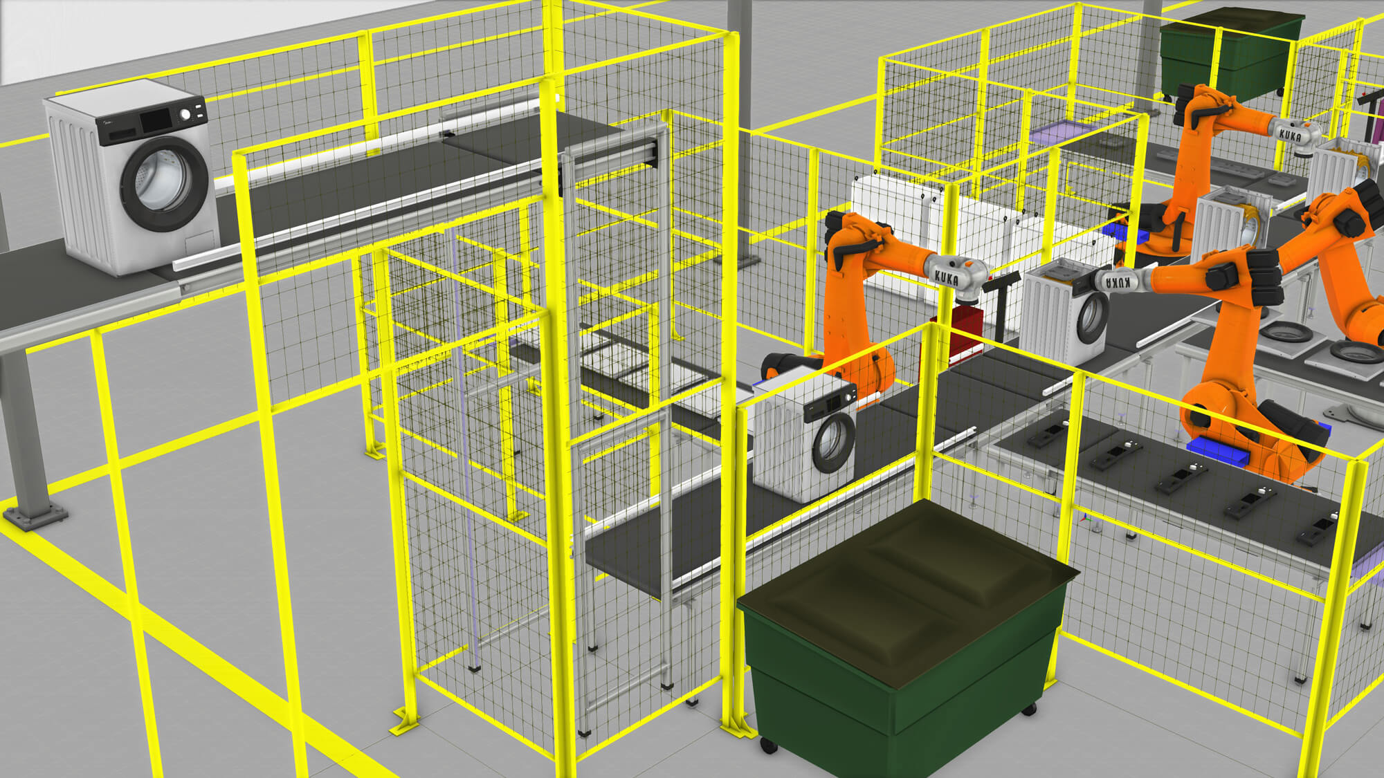
Kong and his team faced two major challenges with this project. The first was how to detect problems during the design phase, and avoid encountering issues during construction and implementation, when it would cost significantly more to solve them. Simulation was key to overcoming this problem. “We used simulation to verify our design,” said Kong. “We aggressively searched for risks in the design and used simulation to minimize or eliminate their effects.”
The second challenge was how to find the best solution to meet the project’s aggressive requirements and targets. Kong’s team used simulation extensively to optimize their design. As an example, they ran more than 100 simulation cases to find the best assignment for workers.
“The methods we used to overcome these challenges were previously unimaginable,” said Kong. “You couldn’t easily come up with the solutions without actually building and testing the line.”
“With Visual Components, we can easily design, simulate, and verify all kinds of solutions in a virtual environment.”
With Visual Components, we can easily design, simulate, and verify all kinds of solutions in a virtual environment.
Kong Fanshi, Ph.D, – Simulation Engineer on the Digital Center team, Midea Group
Exceeding the project goals
With a relentless focus on optimization and improvement, Kong’s team was able to achieve significant improvements and savings from their original design, beginning with more efficient use of the floor space.
“We reduced the floor area for the assembly line by 10 percent, while at the same time increasing production capacity by 10 percent,” said Kong. “The line had sufficient capacity to produce 500,000 units per year.”

The line was able to accommodate mixed flow production of more than 100 SKUs, compared to the normal 5-10 SKUs. Despite the more complex production process, the line was also more balanced. “Line balance was improved by 20 percent, reaching more than 90 percent,” said Kong.

Kong and his team were also able to achieve significant cost savings through more efficient routing and utilization of personnel, such as production, logistics, and quality control workers.
“We were able to reduce headcount by 45 percent from the original plan, without sacrificing output or product quality,” said Kong. “In fact, we were able to improve product quality, reducing the reject ratio from 1,200 defects per million to 120 dpm.”

Finally, Kong and his team were able to accelerate the construction and installation of the full assembly line.
“We reduced the construction period from 15 to 12 weeks, delivering a 20 percent savings in schedule,” said Kong. Total cost savings realized for the project were about $879,000.
“Using Visual Components, we were able to achieve lower investment and labor costs, as well as significant efficiency improvements,” Kong said. “As a result, the total costs of the project were reduced by approximately 15 percent.”

After the line was constructed, the project leader installed a large TV by the assembly line to show how Visual Components impacted the project. It continuously plays a loop of 3D layouts and simulation recordings that Kong’s team created for the project.

Using Visual Components, we were able to achieve lower investment and labor costs, as well as significant efficiency improvements. As a result, the total costs of the project were reduced by approximately 15 percent.
Kong Fanshi, Ph.D, – Simulation Engineer on the Digital Center team, Midea Group
Looking to the future with Visual Components
Following the success of this project, Midea plans to explore how they can further use Visual Components in the design and commissioning of their production systems.
Kong and his team want to customize the software more for their applications and develop their own plug-ins and add-ons. “Visual Components’ open platform and interfaces gives us freedom to extend the applied range of the simulation tools,” said Kong.
Another priority for Kong’s team and Midea is Industry 4.0. They’re looking at how they can digitize their production and make their factories more connected.
“We want to build a digital twin of our production,” said Kong. “We plan to collect machine, logistics, and manufacturing data from the factory floor and visualize it in Visual Components layouts.”
“We also want to explore how we can use Visual Components’ PLC interfaces to deliver commands to our production assets.”
About Midea
Established in 1968, Midea is the world’s largest producer of major appliances and the world’s No.1 brand of air-treatment products, air-coolers, kettles and rice cookers. The company specializes in air treatment, refrigeration, laundry, large cooking appliances, large and small kitchen appliances, water appliances, floor care and lighting.
Midea is headquartered in Southern China, but is a truly global company with over 100,000 employees and operations in more than 200 countries. The company has 21 production facilities and 260 logistics centers worldwide.