Modeling Robots with Visual Components
Ever wondered how we create our robot models? In this article, we explain our process.
Introduction
We often get questions about how we model the robots in our software. In this article, we describe what data is required, the main behaviors used for modeling robots, and how robot models are validated.
What information is necessary?
Our process begins with gathering 3D CAD data and kinematic information for the robot we want to model. The CAD data provides us the geometry data for the robot, and the kinematic information tells us about the robot motion. The kinematic information specification sheets for robots are usually easy to get hold of, whereas CAD data can be more difficult to obtain. We typically get the 3D CAD data directly from the robot manufacturer, their channel partners, or customers. The CAD data can be in multiple formats, including IGES or STEP, but we really just need the geometry data. Some robot manufacturers publish CAD data on their website, but many don’t make this information publicly available.
Kinematic information
Another cluster of data required to model robots is the kinematic information, which helps us understand the robot’s motions, or more specifically, the positions and velocities of the robot’s joints, links, and end-effectors, as functions of time. It usually comes in the form of a spec sheet, which we get from the robot manufacturer. The spec sheet contains schematic data and drawings of different views of the robot. There are also tables that describe the robot’s joint values, limits, speeds, and directions, along with information about the dimensions of the robot links.
Filling in the blanks
While the information provided in these spec sheets tell us a lot about the robot kinematics, there’s usually some additional information we need before we can begin modeling the robot. The process for obtaining this information varies with each robot manufacturer, but it typically involves some extra digging.
- Zero reference position: Most robot manufacturer’s spec sheets show the robot in the ‘home’ position, also known as the reference or master position, but don’t tell us about the joint values and directions when the robot is in this position. The home position is defined differently by each robot manufacturer, which is why we try to get this information for the ‘zero’ position. The zero position describes what the robot looks like when all points are at zero.
- Robot origin: The robot origin refers to the manufacturer specified origin for the robot. For KUKA and ABB robots, the origin is on the floor, whereas for Fanuc and Yaskawa robots, it’s above the floor on the robot’s ‘belly button’. It’s important to note that each robot manufacturer determines the origin for their own robots, and there’s no standardization in how this is defined.
- Directions of base and tool frame: As with determining the robot origin, robot manufacturers have different preferences for defining the directions of the robot mounting plate. Some robot manufacturers follow RIA standards, while others develop their own methods. It’s standard for the Z to point away from the mounting plate, but this alone doesn’t tell us where the X and Y-axis are pointing, or the positive and negative directions of each axis.
- Naming conventions: Most robot manufacturers explicitly define their own kinematic configuration naming conventions, which is a convention for naming standard robot configurations. While we sometimes are given Denavit-Hartenberg parameters, which is a commonly used convention for attaching reference frames to robot links, DH values don’t always provide us with enough information. In addition to these naming conventions, we also need to know the naming of the joints.
- Joint accelerations: Robot manufacturers generally don’t provide information on joint accelerations, as these values depends on many other variables. However, they do provide torque values and joint speeds. Using our knowledge about the kinematic behavior of robots, we’re able to estimate joint accelerations using other information provided by the robot manufacturers.
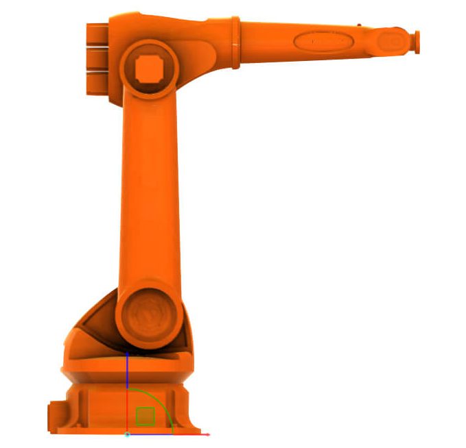
Robot origins
The last step before modeling the robot is to align the robot’s different origins. As previously mentioned, the manufacturer’s origin, or robot origin, is independently specified by each robot manufacturer. We also have our own origin, which we call the Visual Components origin. The Visual Components origin is the same for all robot models in our software, with the Z-axis at the bottom of the floor. The robot models still maintain their manufacturer’s origin in our software, which is important for teaching points and offline programming; but having a standard origin for all robots makes them easily interchangeable.
Modeling the robot
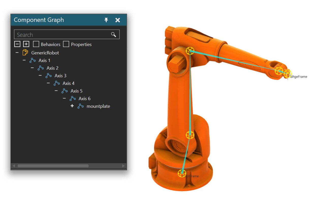
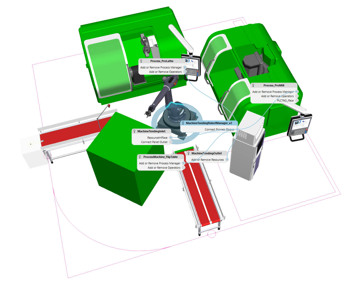
The main behaviors used for modeling robots in Visual Components are ‘kinematics’, ‘robot controller’, and ‘interfaces’. Our robot controller behavior has proprietary motion planners that can be used to parametrically adjust robot behaviors to have a closer match to the characteristics of the robot. The motion planners are generic, in the sense that we use them for all robot models in Visual Components, and greatly simplify the modeling process. The interfaces behavior can be customized to ensure robots are compatible with our plug-and-play standards, that they’re able to snap on pedestals, and can track when attaching end-of-arm tooling.
Validation
In addition to our own internal validation, we typically seek third-party validation of our robot models. If we developed the robot model based on a customer request, we’ll send the component to the customer to validate that the model is accurate. In many cases, we also work directly with robot manufacturers to validate our models.
The typical validation process consists of running a series of download tests: creating a robot program with Visual Components, downloading the program to the robot controller, and running the program on a robot to validate it performs as designed.
Summary
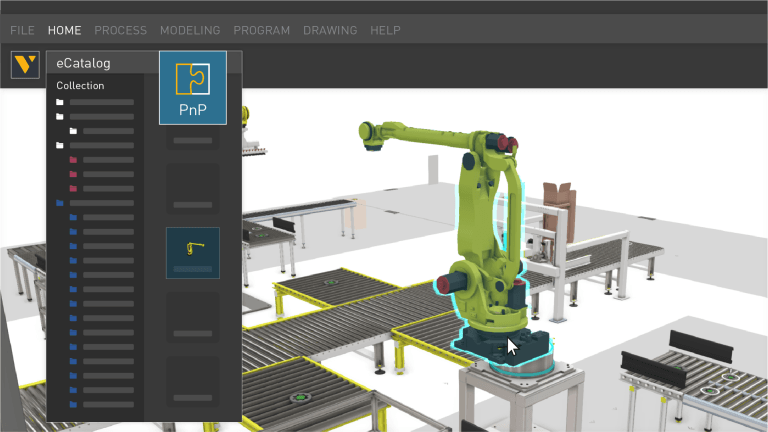
In this article, we gave you a brief introduction to how we model robots with Visual Components. We discussed some of the key information required, the main behaviors used for modeling robots, and how robot models are validated. With more than 1,200 robot models available in our public eCatalog, we provide our users with access to an extensive and constantly growing library of ready-made components.
If you’re interested in learning about how you can use Visual Components to simulate your robot applications, get in touch with us to schedule a free, personalized web demonstration.
Further reading
Leveraging simulation for factory layout design
Explore how discrete event simulation and digital twin technology play crucial roles during the ideation and planning phases of factory layout design. Our software simplifies the design process, providing accurate...
Robot offline programming (OLP): the complete guide (with examples)
This is your complete and comprehensive guide to offline robot programming (OLP). After introducing the topic, it addresses common misconceptions, the problems it resolves, benefits, and real-life example of its...
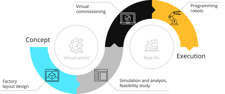
Manufacturing simulation: bring your projects from concept to reality
Manufacturers that commit to the digital transformation inherent in Industry 4.0 will reap the rewards of higher production efficiencies and faster project execution. Together, these will drive growth and profitability...